Masters Degree in Guidance and Navigational Contro...More
Sections
Earthing or grounding is the process of connecting the conductive parts of an electrical installation to the ground or earth. In earthing the metallic parts of an electrical installation such as metallic casing, stay wire, end terminals of cable armour etc. that do not carry current are connected to an earth electrode or conductor buried in moist earth using a thick metal conductor of low resistance for safety. At certain cases the neutral point of the power system is connected to the earth for avoiding the danger at the time of discharge of electrical energy.

Figure1: Electrical Earthing System

Figure2: Electrical Earthing Schematic diagram
The main purpose of grounding is to minimise the unfortunate events like accidents due to electric shock, fire as a result of current leakage through unsought path and ensure the current carrying conductor’s potential does not increase with respect to earth than the designed insulation. In certain cases the metallic parts of the electrical appliances comes in conduct with the live wire, which may be due to the failure of the electrical installation or cable insulation failure. Charges get accumulated in those metallic parts and a person gets a severe electric shock or even death when he comes in contact with such charged metallic parts. By means of earthing these charges can be transferred directly to earth. The following shows the necessity of earthing
Protection of lives of human and animals and also provide safety to electrical appliance and installations from leakage currents.
In case of fault in one phase the voltage in healthy phase need to be constant.
Protect the electrical system and buildings from lightning.
Provides a return path for electrical traction and communication.
Avoid the fire threat in installations.
Earth: The connection of an electrical installation through a conductor to another conductor buried in earth.
Solidly Earthed: An electrical installation or appliance is said to be solidly earthed when it is connected to earth conductor/wire directly without using a circuit breaker, fuse, impedance or any other safety devices or elements
Earth Electrode: A conductor buried in earth for the purpose of electrical earthing is known as earth electrode. The shape of the earth electrode may vary from conductive rod, conductive plate, metal water pipe or any other conductor with low resistance. Earth electrodes are made of copper, galvanised iron, cast iron etc.
Earth Lead: The conductive strip or wire that connects an electrical installation or appliance to the earth electrode is called Earth Lead. Earth lead can be of copper, galvanized iron etc.
Earth Continuity Conductors: They are the conductors used for connecting the earth lead to various electrical appliances and devices such as distribution boards, electrical sockets, appliances etc. It may be in the form of flexible wire, cable metallic covering or metallic pipe.
Sub Main Earthing Conductor: the wire connecting the distribution board to various switch boards. Flexible wires are used as sub main earthing conductor.
Earth Resistance: The resistance between the earth and earth electrode is called earth resistance. It is the resistance of earth electrode, earth lead, earth continuity conductor and earth added up algebraically. The earth resistance is measured using Earth Megger.
According to IEE regulations and IE rules, earth pin in 3 pin plus sockets and 4 pin power sockets must be efficiently and permanently earthed. All metal casings and metal coverings containing or covering electrical supply cable or equipment must be earthed. The metallic frames of generators, transformers, stationary motors etc. must be earth using two separate earthing or distinct connections with the earth. In a dc three wire system, the middle wire must be earthed at the generating station. Stay wires for the overhead electric lines must be connected to earth at atleast one strand to the earth wires.
The main components of electrical earthing system are:
The conductor that connects all metallic part of the electrical installation like the conduit, metallic shells, ducts, plug sockets, distribution boxes, fuses, controlling and regulating devices, metallic parts of transformers, motors, generators etc. and the metallic framework where the electrical components are installed. The earth continuity conductor’s resistance must be very low. As per IEEE rules, the resistance between the consumer earth terminal and the earth continuity conductor must be less and 1 ohms.

Figure3: Earth Continuity Conductor(Cable)

Figure4: Earth Continuity Conductor (bare copper conductor)
The size of these conductors depend on the size of the cable used for the wiring circuit. The cross sectional area of the earth wire must be less than half of the cross sectional area of the thickest wire used in the electrical wiring installation. Generally the size of the copper wire used as earth continuity conductor is 3SWG. Earth wires smaller than 14SWG must not be used. In certain situations copper strips are used instead of bare copper conductor.
The conductor connecting the earth continuity conductor and the earth electrode is called earthing lead or earthing joint. The point where the earthing lead meets the earth continuity conductor meet is called connecting point. The earthing lead must be straight, lower in size and must have minimum number of joints. Eventhough copper wires are generally used as earthing lead, copper strips are preferred for high installation as it can carry higher values of fault current due to its wider area. Hard drawn bare copper wires are also used as earthing lead. In that case all earthing conductors are connected to the connecting point and the earthing lead is used to connect earth electrode to the connecting point. To provide increased protection to the electrical installations, two copper wires are used as earthing lead to connect the equipment’s metal body to earth electrode or earth plate. If there are 2 earth electrode there should be 4 earthing leads. This isn’t for providing parallel path for fault current but for carrying fault current simultaneously giving added safety.

Figure5: Copper strip used as Earthign Lead

Figure6: Galvanised iron strip used as Earthing Lead
The area of cross section of the earthing lead should not be less than half of area of cross section of the thickest wire used in the installation. The largest size of the earth lead is 3SWG and the minimum size should not be smaller than 8SWG. If the load current in 200A from the supply voltage then copper strip is preferred over double earthing lead.
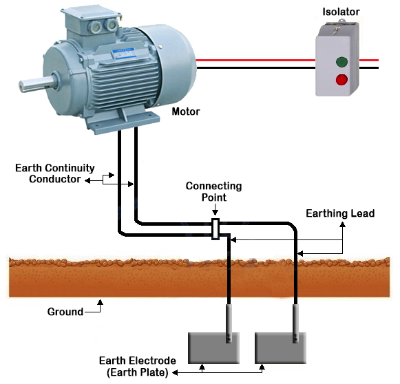
Figure7: Double Earthing for Motor
The final part of the earthing system which is buried underground which is connected to the earthing lead is known as the earth electrode or earth plate. Earth electrode can be in the form of metallic rod, pipe or plate which has very low resistance in order to carry the fault current to the ground safely. The earth electrode can be of copper or iron (galvanized) . The earth electrode must be buried in moist ground and in case the moisture content of earth is low then put water in the galvanized iron earth electrode. The earth electrode is always put in the vertical position. Layers of charcoal lime and salt is put around the earth electrode or earth plate. This helps in increasing the size of the earth electrode and also helps in maintaining moisture around the earth electrode or plate. For effective earthing action the earth electrode must be 4 meter long.

Figure8: Earth Electrodes
Following are the types of earthing system used:
Plate earthing
Pipe earthing
Rod earthing
Earthing through waterman
Strip or wire earthing
Plate Earthing
In this type of earthing, a plate made up of galvanized iron or copper is buried vertically at a depth not less than 3m from the ground level. The dimension needed for galvanized iron plate is 60cmX60cmX6.35mm and that for copper plate is 60cmX60cmX3.18mm.

Figure9: Plate Earthing
It is the most common type of earthing system. In this type of earthing system, a perforated pipe made of galvanized steel/iron of approved length and diameter is buried vertically. The size of the pipe used depends on the magnitude of current and the amount of moisture content in the soil. The diameter of the pipe is usually 40mm and length 2.75m for normal soil. The amount of soil moisture determines the length of the pipe.

Figure10: Pipe Earthing
Rod earthing is similar to pipe earthing. In this method of earthing a copper rod of diameter 12.5 mm or 16mm diameter galvanized steel or a hollow section of 25mm galvanised iron pipe of length not less than 2.5m is buried vertically underground. The pipe can be buried manually or using pneumatic hammer. The earth resistance is reduced to a desired value by the embedded electrode.

Figure11: Rod Earthing

Figure12: Rod Earthing with Charcoal Salt mixture filling
In this type of eathing system, the water main (galvanized iron) pipe is used for earthing. The resistance of the galvanized iron pipes are checked and earthing clamps are used to minimise the resistance for earthing connection. If standard conductors are used as earth wire, end of the strands are cleaned. The earth wire must be straight and parallel to water main pipe to make firm connection possible.

Figure13: Earthing through Water Mains
In this type of earthing, a strip electrode of cross section not less than 25mmX1.6mm is buried in a horizontal trench of depth not less than .5m. If copper is used then the desired cross section is 25mmX4mm and if galvanized steel/iron is used then the desired cross section is 3mm2. When using round conductors made of galvanized steel or iron, the cross sectional area should not be less than 6mm2. The length of the conductor buried should not be less than 15m.
When the potential between two clouds or between earth and cloud reaches a sufficiently high value, about 10000V/cm, it results in ionization of air along a narrow path and lightning flash. The possibility of discharge is very high on tall trees or buildings rather than the ground. The buildings are protected from lightning strikes using metallic rod extending to the ground from a point above the highest part of the building. The conductor has a pointed edge on one side and the other side is connected to a long thick copper strip that runs down the building. The lower end of the strip is properly earthed. During a lightning strike, it hits the metal rod and current flow down through the copper strip. The metal rod provides a low resistance path for the lightning discharge and prevents it from traveling from the structure itself.

Figure14: Lightning Protection

Figure15: Copper Spikes used as Lightning Rod

Figure16: Lightning arrester on Communication tower
The earthing arrangement connected to the lightning arrester’s copper strip must not be connected to the earthing arrangement made for the electrical installation earthing. The copper trip should be laid in such a way that it does not come in contact with the building.


Sections


Copyright © 2024 Mepits - Designed By Digiora

